A Comprehensive Guide to Bonding and Grounding 2.0
January 26, 2022
As one of America's Founding Fathers, Benjamin Franklin has long been recognized for a great number of occupations and talents—diplomat, philosopher, scientist, and inventor just to name a few. However, it is one of Franklin's most instantly recognizable moments, which is to some degree mythical, that simultaneously captures both the sense of childlike wonder and important scientific curiosities that endures to this day, FLYING A KITE IN A THUNDERSTORM.
In Franklin's quest to prove lightning as a form of electricity, he set out on a stormy afternoon with nothing but a silk kite, string, wire, metal key, and a hunch. While the kite was not struck by lightning on that infamous afternoon, Franklin was successful in proving that the lightning held an electrical discharge when he noticed that loose threads from the string were standing on-end 'just as if they had been suspended on a common conductor," according to subsequent accounts by one of Franklin's colleagues, the British scientist, Joseph Priestly.
Furthermore, when Franklin put his finger near the metal key, also suspended from the string, he recounted feeling a spark when negative charges in the key became attracted to positive charges in his hand. While he did not know it at the time, Franklin's observations also confirmed that the electricity from the storm could be charged over a conductor (the metal key) into the ground, providing a safe alternative path to the earth. Sound familiar?
While not nearly as whimsical as Franklin's kite in a storm, but no less important, today's
National Electrical Code (NEC) defines grounding as intentionally connecting to earth (Code®, 2020), such as ground rods and water pipes. Bonding, meanwhile, is the effective joining of metal items, which could be achieved by a conductor or anchoring hardware (e.g., nuts and bolts). From a high level, it is proper to say that grounding is to provide a reference, an electrical anchor, and bonding is achieved to equalize potentials between metal surfaces. Simple enough, right?
For this discussion, consider the components as the Grounding Electrode System (e.g., ground rods), the Equipment Grounding System, also known as the safety ground, (e.g., metal frames on panelboards and third prong on outlets), and the Telecommunications Bonding Infrastructure (e.g., busbars and bonding conductors), which features busbars and other components present in the telecom rooms. Simplifying it even further, electricians ground electrical systems and telecommunications professionals simply bond.
Beyond the basics, the electrical protection of today's high-speed cabling systems is an essential part of a properly designed and installed ICT infrastructure. A bonding and grounding system will aid in controlling negative influences, such as electromagnetic interference (EMI), electrostatic discharge (ESD), and ground potential rise (GPR) from lightning.
It is important, however, to keep in mind that there are various factors at play that can generate confusion:
- The industry currently relies on anecdotes, not data. This is a slippery slope because it creates the illusion that everyone is an expert, while lacking actual proof of what works. Without data, speculation reigns and resolution is sought but never achieved with testing, maintenance, or solutions.
- Bonding and grounding fall into a gray area for most low-voltage professionals. Although electrical bonding is required by code in the cases where other methods fall short, telecommunications bonding infrastructure is only encouraged but never required by a code.
- Documents supporting a particular design can be confusing and leave little room to expand beyond certain applications.
- Some believe their bonding infrastructure must evolve at the same pace as their technology, leading them to overcomplicate the methods of achieving it, while others want to keep things simple. Simplification is the key.
- Lastly, because telco bonding is a close cousin to the electrical realm, it can be intimidating by adding mystery and danger to the subject. This perception results in a gray area of how different industry professionals perceive how electricity works. Uncertainty brings more conflict.
LOOKING TO THE STANDARDS, INCLUDING THE LATEST UPDATES TO TIA-607
Keeping misconceptions in mind, it is important to counteract with industry best practices.
For highly detailed and comprehensive references to codes, standards, methods, and best practices used in telecommunications bonding and grounding systems, refer especially to chapters eight and ten of BICSI's
Telecommunications Distribution Methods Manual (TDMM), 14th edition. The chapters are derived from documents, such as ANSI/BICSI N3-20
Planning and Installation Methods for the Bonding and Grounding of Telecommunication and ICT Systems and Infrastructure, as well as ANSI/TIA-607, ISO/IEC 30129, NFPA 70, NFPA 780, and publications by IEEE. Additional standards related to bonding and grounding (earthing) are found in
TDMM's Appendix A.
To address the scope, purpose, and timeliness of this article, focus on ANSI/TIA-607 is most relevant and important. According to the Telecommunications Industry Association (TIA), TIA-607 provides guidance on generic telecommunications bonding and grounding (earthing) for customer premises. As recently as July 2021, the standard has been updated to provide the basic principles, components, and criteria that telecommunications bonding and grounding systems within a building share one electrical potential.
The naming conventions provided in the standard are consistent with the expectations surrounding each of the terms. For instance, the telecommunications grounding busbar (TGB) never really grounded anything. Therefore, it is now called a secondary bonding busbar (SBB). In part, ANSI/TIA 607-C adopted the new term to harmonize with ISO/IEC 30129 terminology and that of the European Union's CENELEC standards that better clarify the purpose of components. The terminology change helps establish a clarity to purpose and practice, allowing design and deployment mindsets to follow suit. If ICT professionals and installers worldwide understand the purpose of bonding, the practice will fall into place accordingly.
Ultimately, the purpose of the bonding infrastructure is to aid in equalizing potentials during lightning strikes, electrical system fault, electrical static discharge, radio frequency interference (RFI), and electromagnetic interference (EMI). Think of a telecommunications room (TR) or data center as ships on the ocean.
In order to ride the waves of energy, everything must rise and fall at the same rate and amplitude. Therefore, the bonding infrastructure is the mechanism that can help achieve this. Because they are the central point for ground connections and they conduct a substantial amount of current of electricity, grounding busbars are an essential element of TRs.
However, in a reality where density and virtualization are on the rise, it is now crucial that racks and cabinets include features that can and will ease the installation process. This can include a selection of racks and cabinets that feature integrated bonding points and easy hardware assembly for bonding, so installers do not need to worry about removing paint or dealing with fallen metal flakes around or above critical IT equipment (Figure 1).
Additionally, it is important to consider how large-scale, rapidly occurring electric arcing can be a significant contributor to data disruption and damage to equipment. In minor cases, more lasting damage to equipment can happen. No matter the outcome, having a reliable bonding and grounding system in place and controlling the ESD and surge paths will most certainly aid in minimizing the impact and/or damage to equipment.
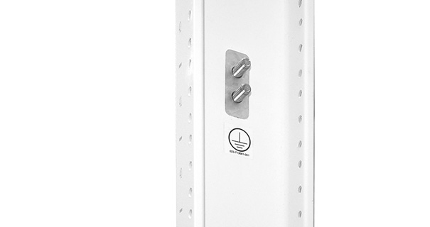

FIGURE 1: Listed Integrated bonding points on painted metal infrastructure eliminate the need for installation professionals to field modify or fabricate bonding connections, while also providing a convenient test point.
MISCONCEPTIONS AND CABLE URBAN LEGENDS ABOUT BONDING OR GROUNDING ICT INFRASTRUCTURE AND EQUIPMENT
Much like the day Benjamin Franklin flew a kite, the difference between fact and fiction can warp and bend over time. Here are some additional misconceptions that continue to persist about bonding and grounding ICT infrastructure and equipment:
- Telecommunications bonding is for safety and lightning protection—not true. The bonding infrastructure will not enhance safety nor is it necessary for lightning dissipation.
- The metal frame of a building is not a good bonding conductor—completely false.
- Current only takes the path of least resistance, leading people to install larger conductors, thinking the bonding will be better—nope. The size of the conductor is not helpful; it is how it is routed.
- An equipment grounding system is dirty and a poor bonding plane—also not true.
- The trouble with recency bias is that every site seemingly winds up having to look like the last one—it is wrong to think that every design must follow the same methods and layouts.
Simply put, incorrect methods of bonding can cause hazardous potentials. One of the primary concerns relating to these misconceptions is when more ground rods get driven into the floor of a data room or telecommunication space. Knowing how to steer clear of these potholes must originate from better and newer education on the subject.
WHAT REALLY, THEN, ARE BEST PRACTICES?
When taking a closer look, more misconceptions are discovered about traditional bonding and grounding. It can be easy to lose sight of what should, does, and has worked. Consider the following:
Every site is unique, so designers and installers should treat them as such. For example, make building steel the focal point of the bonding connection. If steel is not available, go to an electrical panelboard. If a panelboard and steel are not available, use bond busbars to the outlet boxes or conduits that feed them. By finding the reference for the bonding infrastructure in the room or as close as possible, conductor lengths and sizes will be kept to a minimum.
Remember that there is no reason to run a telecommunications bonding backbone (TBB) when building steel and/or an electrical panel board is present. It is an antiquated approach and has never effectively worked. The building steel and/or the equipment grounding system takes care of that (Figure 2).
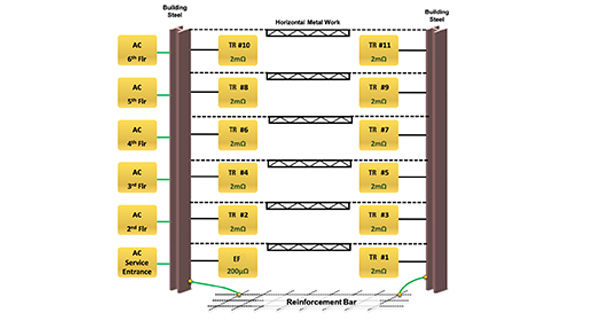

FIGURE 2: Building steel or metal frame in a multi-story building achieves bonding between rooms and floors and is often a much more effective method to ensure proper equalization of potentials between building systems over the antiquated approach of relying on a telecommunications bonding backbone (TBB).
A little-used practice is making sure the threaded parts of the bolts on the busbars are facing out, not back towards the wall. Torque is always checked on the threaded nut end anyway, so why not make it more accessible? Also, consider lugs that can be terminated on the same end as the nut, not on the end where the bolt head resides. One may never get effective torque without it (Figure 3).
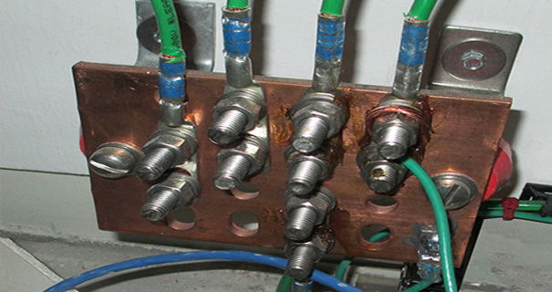
FIGURE 3: A proper view of the "threads out" practice that follows standard Society of Automotive Engineers (SAE) torque requirements, which ensures easier accessibility when checking torque.
If not done already, implement a preventative maintenance plan and know when to use it. Include checking all bonding connections during the scheduled walk throughs. Many site survey clients have not done this in the past and, in retrospect, wish they had.
Consider the metal infrastructure (e.g., trays) as part of the mesh bonding infrastructure. This reduces the numbers and lengths of conductors.
Do not run bonding conductors greater than 10 m (~33 ft) and expect them to do what is intended.
Regardless of the design, be sure that it is maintained and tested. Even if it is a secondary benefit to a site environment, it should not become a problem with a lack of maintenance.
In the ICT industry, it is known that the primary bonding busbar (PBB) serves as a central attachment point between the telecommunication bonding infrastructure and the building electrical grounding system.
Here is a simple and effective checklist of the other key system components:
PBB and SBB
For each equipment room and telecommunications room, select a PBB and SBB with sufficient connections for the racks and tray in the room. Consider enough bonding points for the client's plan for future growth as well.
Rack Bonding Busbar
For racks and cabinets, use a rack bonding busbar (RBB) to provide an equipotential plane to protect equipment and patch panels that require bonding to the SBB.
Conductors
Insulate copper conductors used to connect busbars, racks, and cable trays. Metal cable trays and cable runway (e.g., ladder rack) can be used as the conductors when bonded across splices. Building structural metal can also be used to bond to the building's grounding electrode system.
Connectors
Include all types of mechanisms used to connect conductors, busbars, racks, cabinets, cable tray, and runway. Examples include exothermic welds, compression lugs and taps, pedestal clamps, pipe clamps, beam/flange clamps, terminal blocks, pathway splicing hardware, and integrated bonding points on racks and cabinets.
Labels
It is important to identify each conductor by labeling, and note that it should not be loosened or removed.
HOW TO TEST THE BONDING CONNECTION
When testing a bonding connection, it is useful to think of busbars as the window to the soul for the rest of the room. They should be inspected first for potential problems, such as loose connections.
The first step is to test for ac and dc current. From there, make it a priority to determine the ac and dc current measurements. The ac current measurements are necessary to pinpoint areas where outlet wiring is not compliant. The dc current measurements are made to track corrosion sources and/or failing power supplies on uninterruptible power supply (UPS) units, routers, switches, and other equipment.
Then, utilize the two-point test method to verify the bonding effectiveness. This requires the use of a micro-ohmmeter connected between any two points to verify that the resistance between those two points is less than 100 milliohms or 0.1 ohm. A common best practice is to test from the busbar to the furthest point in the room. Most of the connection points between busbars, rack, tray, and other components should and will be sufficient, but there is always a possibility that there will be that one loose connection that makes the extra effort of testing all the more worth it.
Also, do not forget that micro-ohmmeters have greater resolution and are a fraction of the cost of earth ground testers; unfortunately, earth ground testers are what most technicians are still using today. Use a half-step method that starts at the half-way point of the connections. Then, test from that starting point down the line, which will narrow the scope of observations and more easily pinpoint the source of a fault.
BONDING AND GROUNDING 2.0 - A BETTER BEST PRACTICE
What is it about the things taken for granted, after all? Just as the story of Benjamin Franklin flying a kite in a thunderstorm endures because of its literal flight of fancy, has it not also become a figurative lightning rod for why it is important to dispel rumors and myths when the story becomes too fantastic for its own good?
For many years, the best practices of bonding and grounding have been a series of educated findings that allow everyone to benefit, build upon, and follow suit—making small modifications along the way and always working to improve upon what has come before.
Pertaining to bonding and grounding, this has meant holding on to the accepted understanding that parallel paths never really meet until they reach the busbar, thereby resulting in all circuits relying on just one main connection to that busbar. The inherent difficulty that emerges is the fact that there can be different gauge effects and loose serial connections that result in different potentials between the runway and the rack bonding systems.
From this perspective, when searching for new ways to bond cable runways, racks, and cabinets that minimize labor and controls cost, it is wise to pursue a system that helps industry professionals meet project requirements, improve everyone's overall fundamental understanding of bonding, and more easily accept and adopt improved best practices when they arrive, while looking for ways to improve upon what has come before.
ICT professionals must also work to ensure that any fundamental changes in the field can be easily taught and learned or the industry risks losing a better best practice to the fringes of progress. Perhaps one of the best practices is that of the mesh bonding topology, which uses a series-parallel circuit rather than multiple series-bonding circuits (Figure 4).

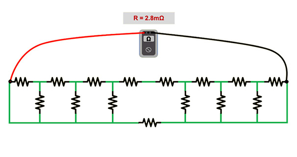
FIGURE 4: A graphical representation of a mesh bonding topology or series-parallel circuit with many parallel paths with interconnections and an overall resistance of just 2.8 microhm.
A mesh bonding topology improves circuit performance because the net effect of bonding everything together is to lower the overall resistance in the circuit. Each parallel addition reduces the overall resistance. Significantly less than established threshold can be demonstrated through measurement with a micro-ohmmeter.
Installation can take a lot of time, time that installers these days simply do not have; and time is money. Installers need to utilize a solution that will ensure bonding integrity. They also need products that will help them remain safe.
It is important to remember that any onsite, in-field fabrication on ladders and overhead of equipment can always introduce an element of increased risk of falls and injury.
Additionally, installers, at times, have to modify the cable runway, which takes even more extensive amounts of time and labor.
When drilling to install straps is required, there are metal shavings that can introduce new opportunities for equipment damage to occur. Using the principle of a mesh bonding topology creates that series-parallel circuit across the room discussed earlier. In this case, field testers only show continuity. A micro-ohmmeter can then reveal the massive difference in resistance.
This approach allows the design to eliminate a number of traditional components, purely by having the foresight to effectively combine those components together. Thus, a new kind of mesh bonding topology is born (Figure 5).
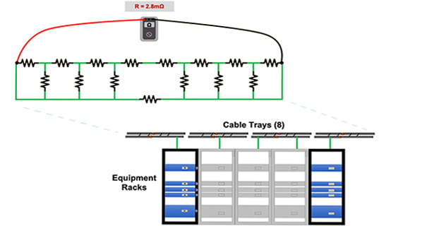

FIGURE 5: By combining components together, a new kind of mesh network topology that uses interconnected and bonding cable trays and runway ensures a faster, safer, easier, more efficient, and better performing method for bonding and grounding in the data center and beyond.
It is here, at this juncture, where ICT professionals can build upon what has come before and make it better - not by tearing down the past but by building it back up, better. Benjamin Franklin would approve!